Why I decided to build my own
Basically, the GPX instrument cluster does its job, but it has four fucking awful drawbacks:
- In direct sunlight, you can’t see shit.
- When the speed crosses from one whole km/h value to the next, the digits flicker like crazy. Apparently, the programmers have never heard of hysteresis or how to use it.
- The fuel gauge is so unclear that even in the dark, it takes a moment to work out how much fuel is left in the tank.
- And why the fuck does the speedometer read 10–15% too high?
These frustrations are part of the reason I decided to build my own instrument panel, without these infuriating drawbacks.
Two instruments, eight needles
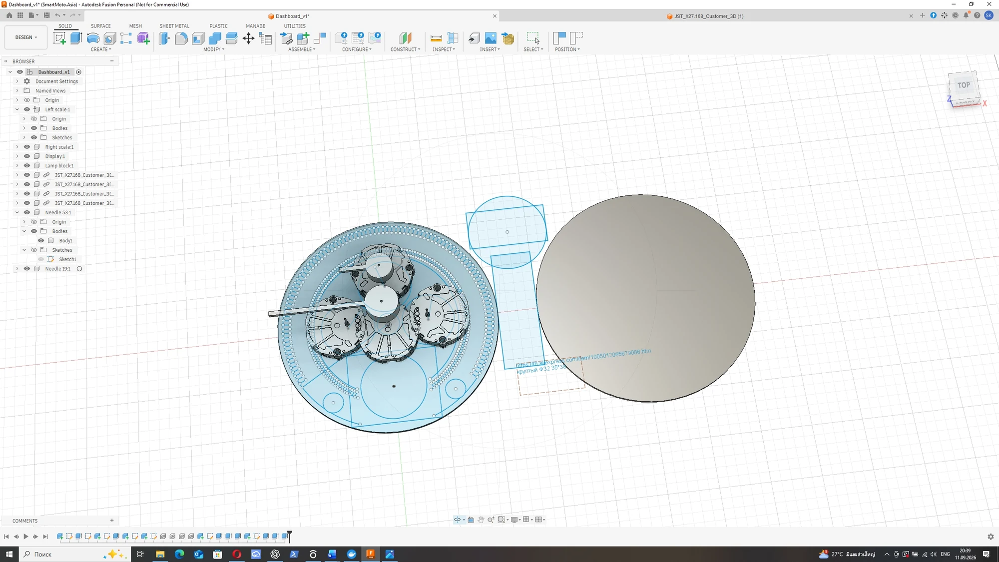
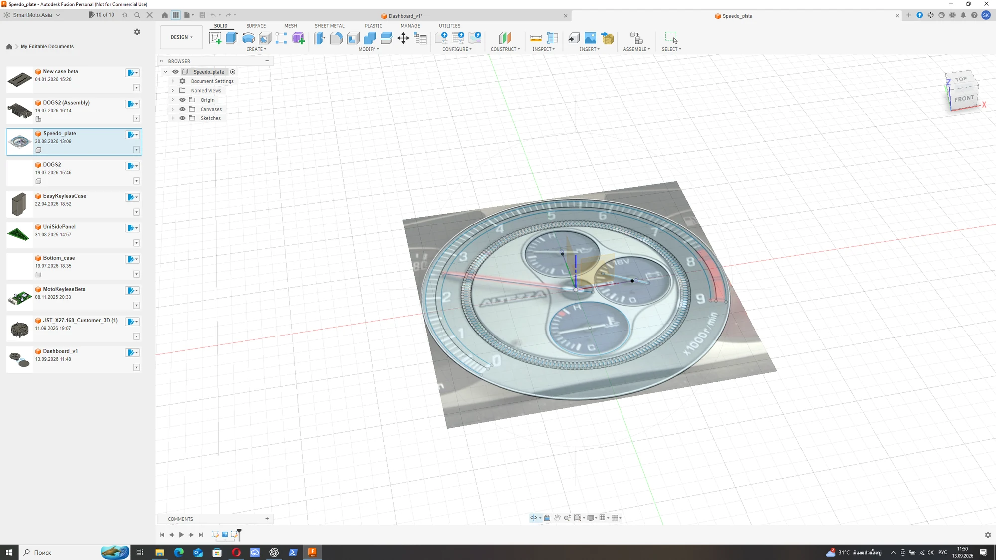
My starting point is a pair of large, round instruments. Each will have four analogue needles and a round LCD. I want the main riding information to be readable from the needles, with the displays providing space for additional information and a configurable interface.
| Left instrument | Right instrument |
|---|---|
| Tachometer | Speedometer |
| Clock | Voltmeter |
| Front tyre pressure | Fuel level |
| Rear tyre pressure | Selected gear, indicated by a needle |
The gear indicator is part of the analogue design too: a dedicated needle will point to the selected gear. The two tyre-pressure readings will each have their own needle in the left instrument.
Working out the mechanical layout
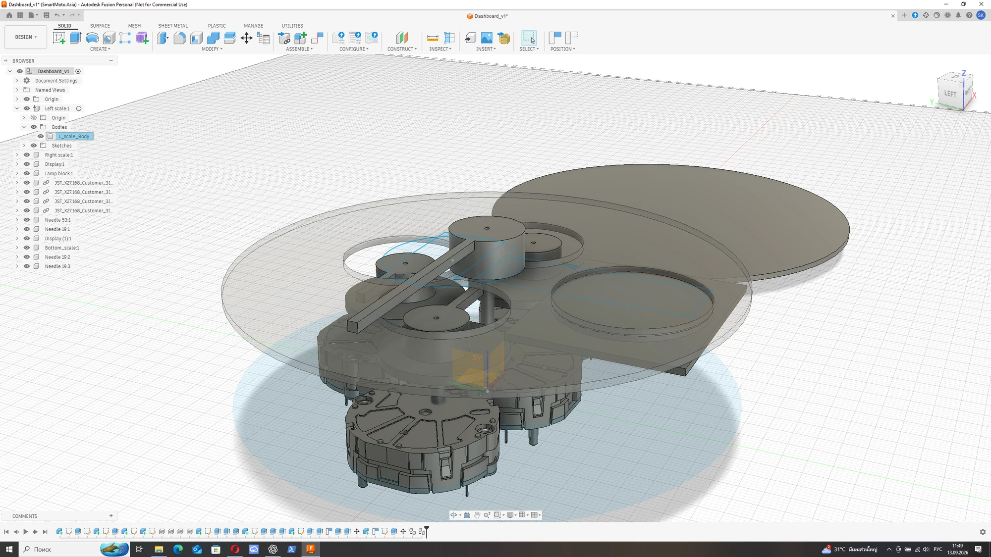
These CAD views show the work behind the dial face: the gauge movements, needle heights and the space for the display. I’m developing the mechanical arrangement alongside the electronics.
The electronics behind the dials
The architecture I’m developing uses a central ESP32 and two identical STM32 instrument modules linked over RS-485. Each local module is intended to handle four gauge stepper motors, one display, addressable RGB lighting and the local buttons.
The ESP32 will handle the overall application logic and generate the display content, while the STM32 modules handle the local hardware. This arrangement should let me change the interface and graphics on the ESP32 without having to rewrite the firmware in both instruments.
Arduino and open source
I’m designing this as an open-source project, with Arduino-based firmware for both the ESP32 and STM32, developed in PlatformIO. The intention is to make the code available so that other builders can study it, adapt the behaviour and create their own display layouts.
Arduino provides the common development framework; where needed, I can also use the STM32 hardware libraries and direct register access for timing-sensitive work. The project is still taking shape, so the source release will follow as the design develops.
A connection beyond the motorcycle
I also plan to give the panel internet access so it can exchange information with my home server and an AI agent. That connection is part of the intended architecture; the exact functions and interaction are still to be developed.
At this point—and development is still at a very early stage—these are the features I would like to implement:
- Fuel consumption and remaining range. Estimate fuel consumption by integrating fuel-injector pulse durations. Combined with AI-tracked refuelling—my AI already scans my receipts for budgeting, so it knows about every fill-up—this should allow very accurate predictions of the remaining range.
- Motorcycle data on my smart home server. Send information about the bike’s condition and the routes I ride to my smart home server.
- Rain forecasts and fuel-aware navigation. Use AI, the route from the navigation app and a weather service API to provide real-time rain forecasts along the route, and plan routes around the need to refuel.
- Phone notifications on the instrument panel. Show incoming calls and message notifications on the panel’s display. I’m not so permanently online that I want to ride with a headset, but sometimes it is useful to know who is trying to reach me.
What I’m working on now
The work has begun with the mechanical layout and the division of responsibilities between the controllers. The CAD model is an early step in fitting four gauge movements and a display into each instrument.
Power management is another part of the design: I want the clock to keep time with the ignition off, waking its controller briefly to advance the needle, while the rest of the system spends most of that time asleep. Coordinating wake-up from the ignition and buttons is one of the details I’m working through.
This is the beginning of the development, with the layout, electronics and firmware still evolving. I’ll add the prototypes, measurements and design changes here as the work progresses.
Part of my GPX 250 Twin Brighton workshop journal.
Back to all modifications