Part 01
Removing the cluster
The first step was to reach the wiring without making changes to it. These are the removal steps recorded for my GPX 250 Twin.
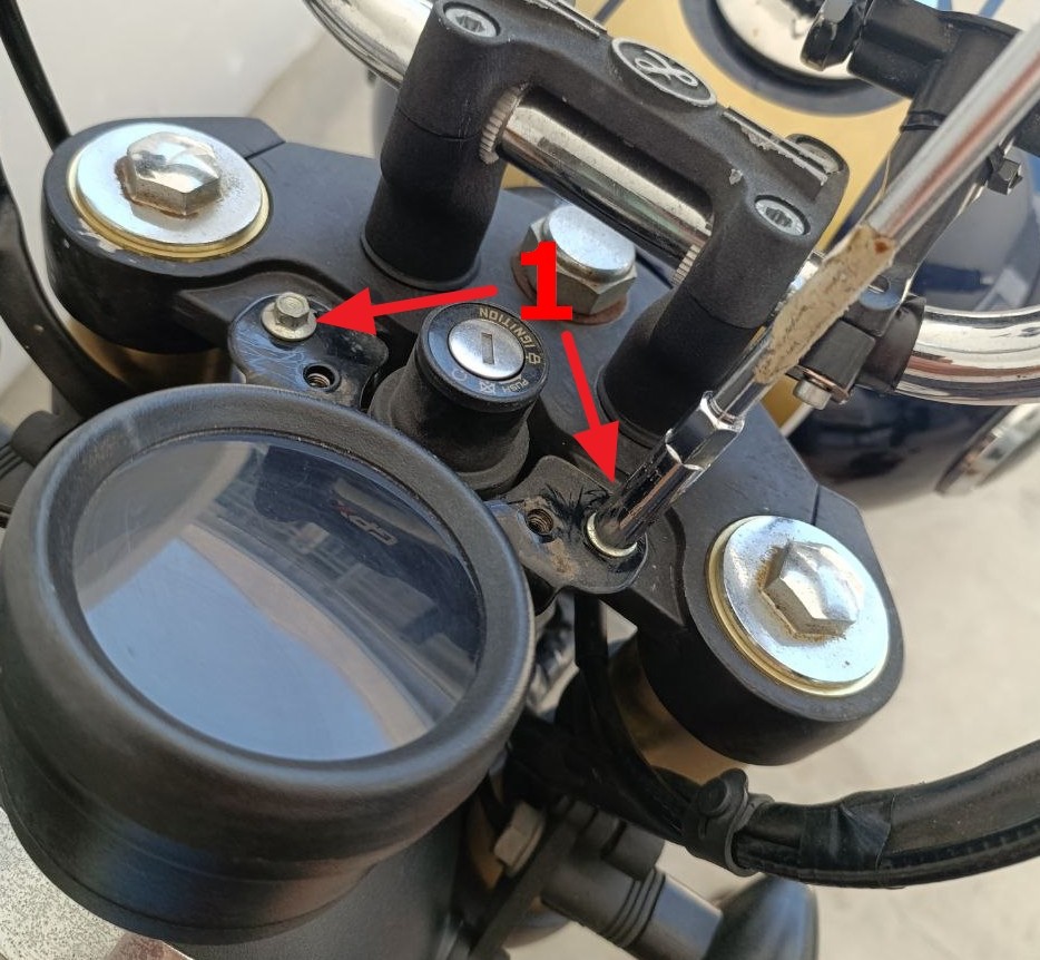
- Remove the two Phillips screws securing the plastic trim around the ignition lock, then lift the trim away.
- Use an 8 mm wrench to undo the two bolts securing the instrument-cluster bracket.
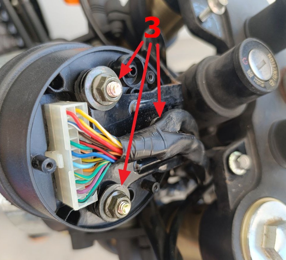
- Turn the cluster over and remove the three small screws securing its lower cover.
- Lift off the cover to expose the 20-pin, two-row connector.
- Disconnect the connector and remove the cluster.
- If needed, remove the three bracket nuts with an 8 mm wrench.
Reinstallation follows the reverse sequence.
Part 02
Connector map and bench power
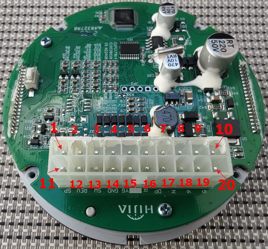
The connector is a 20-pin Molex Mini-Fit Jr. type with a 4.2 mm pitch. My notes identify the following signals. The diagram shows the connector orientation used for this pin numbering.
| Pin | Function | Notes from this cluster |
|---|---|---|
| 1 | Fuel sensor | 5 V through a 220 Ω resistor |
| 2 | Speed-sensor supply | 5 V through a 220 Ω resistor |
| 3 | 1st gear | Active when grounded |
| 4 | 2nd gear | Active when grounded |
| 5 | 3rd gear | Active when grounded |
| 6 | 4th gear | Active when grounded |
| 7 | Left turn indicator | +12 V activates the indicator |
| 8 | ABS indicator | Not fitted on this version |
| 9 | Battery positive | Permanent supply for the clock |
| 10 | Ignition positive | Switched +12 V for cluster operation |
| 11 | Speed signal | Approximately 3.5 V amplitude |
| 12 | Tachometer | Approximately 12 V amplitude; 40 ms period at 1,500 RPM |
| 13 | SW | Not used on this version |
| 14 | Ground | Supply return |
| 15 | High-beam indicator | +12 V activates the indicator |
| 16 | Right turn indicator | +12 V activates the indicator |
| 17 | Check Engine indicator | Active when grounded |
| 18 | Neutral | Active when grounded |
| 19 | 6th gear | Active when grounded |
| 20 | 5th gear | Active when grounded |
Powering it away from the motorcycle
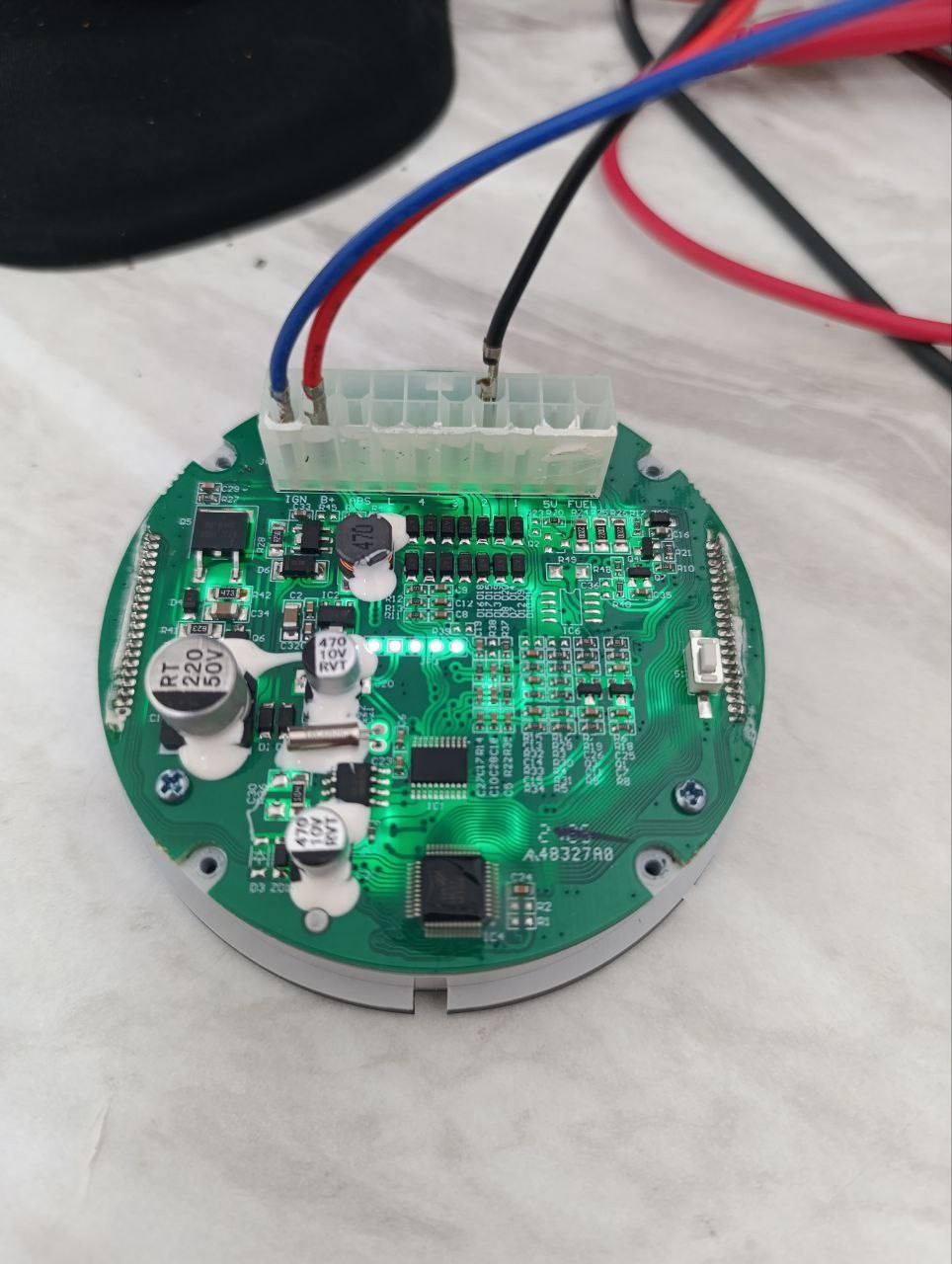
For the bench setup in my notes, +12 V goes to pins 9 and 10, with ground on pin 14. This separates cluster investigation from the rest of the bike. Check the connector orientation against the photograph before using the pin map.
Part 03
Opening the housing and tracing the inputs
The glass surround is held by locating slots and sealant. It needs a small counter-clockwise rotation before it can lift off. This was the most difficult part of disassembly.
With the surround removed, undo the four screws recessed into the underside. Push the board and display assembly upward from below. Do not lever the display from its upper edge.
What I found inside
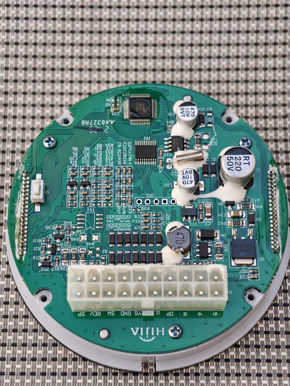
- A microcontroller with its marking removed. It resembled a CH32V003F4P6, but that identification is unconfirmed.
- A real-time clock, without a separate backup battery on the board.
- An LCD controller.
- A DC/DC circuit driving the LED backlight.
- A 3.3 V regulator for the processor.
- Input conditioning for the digital and analogue signals.
The circuits I needed to understand
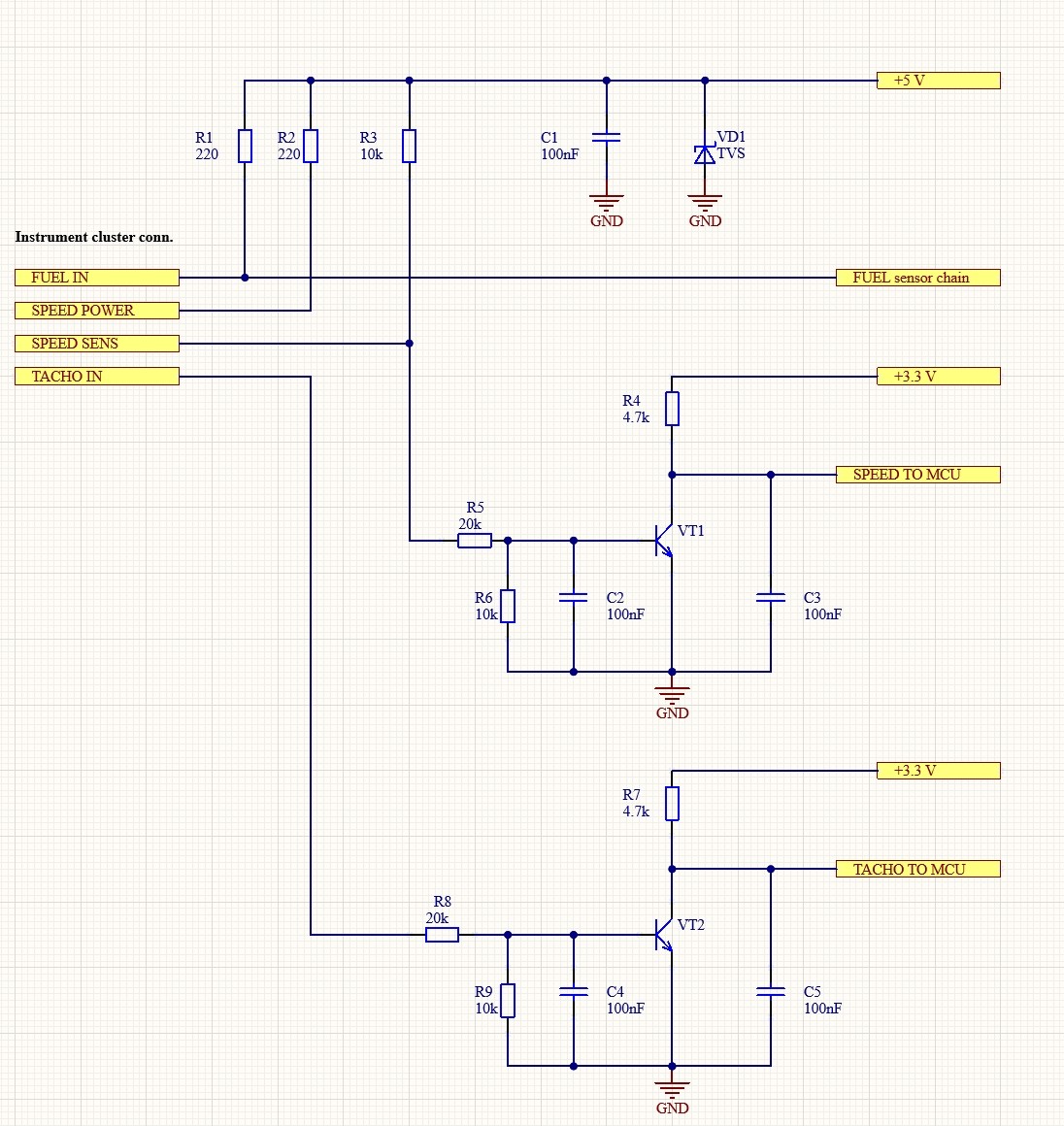
I traced the speed and tachometer input circuits because they were directly relevant to the trip computer and automatic turn-signal cancellation. This is a reconstruction of those input circuits, rather than a complete manufacturer schematic.
What this investigation gave me
A connector map, observed signal levels and a view of the input circuitry make the next design decisions much less speculative. They also provide a useful reference when the cluster needs to be tested away from the motorcycle.
Kilometres or miles?
Did you know that, with the ignition on, you can press and hold the button underneath the instrument cluster for three seconds to switch the speed and distance readings from kilometres to miles and back?
Why I decided to build my own
Basically, the GPX instrument cluster does its job, but it has four fucking awful drawbacks:
- In direct sunlight, you can’t see shit.
- When the speed crosses from one whole km/h value to the next, the digits flicker like crazy. Apparently, the programmers have never heard of hysteresis or how to use it.
- The fuel gauge is so unclear that even in the dark, it takes a moment to work out how much fuel is left in the tank. What twisted design genius thought it was a good idea to make the fuel-gauge segments GREY on a BLACK background, on a display that wasn’t exactly bright to begin with? You can’t see them even at dusk.
- And why the fuck does the speedometer read 10–15% too high?
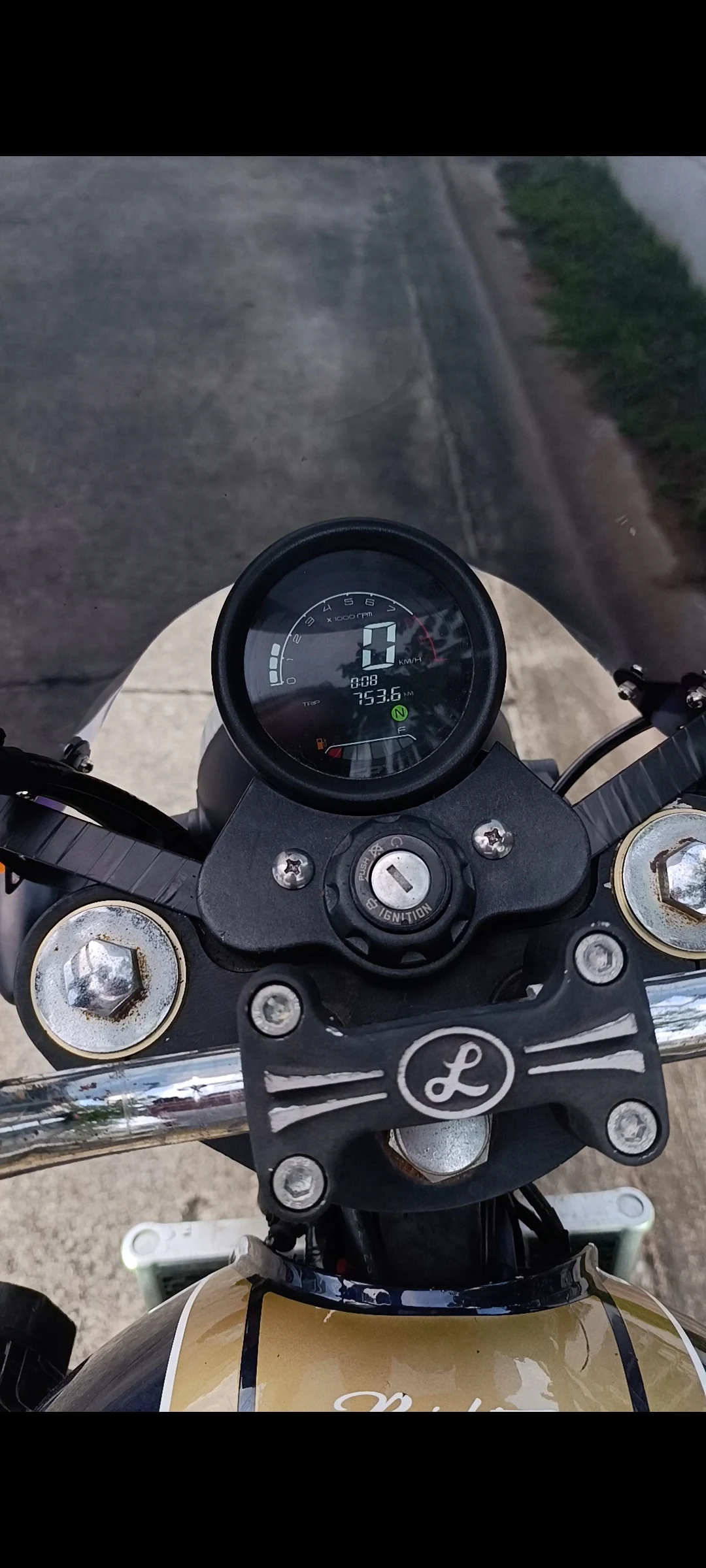
These frustrations are part of the reason I decided to build my own instrument panel, without these infuriating drawbacks.
Part of my GPX 250 Twin Brighton workshop journal.
Back to all modifications